Bringing the Schooner Zodiac into the Digital Age for its 90th birthday with Geomagic Design X scan-to-CAD software
In 2012, engineer Christian Stark took his family on a sailing trip around the San Juan Islands in the Pacific Northwest in Washington State, and fell in love with the 90 year-old 127 foot Tall Ship, the Schooner Zodiac . On a second cruise as volunteer crew, Christian was discussing the ship’s sailing performance and the skipper noted that the ship’s performance on a portside tack to a starboard tack were perceptibly different. In addition, the skipper mentioned to Christian additional port side structural damage that had been repaired in an earlier renovation
Christian’s engineer brain went into action. He started asking about blueprints, about hull scans, proposing the idea to actually measure the difference in shape between port and starboard. However, the blueprints had been lost in a fire at the shipbuilders many years ago and the only drawings that existed were approximated hull line drawings created for CoastGuard certification. And these drawings assumed that both sides of the hull were exactly the same. How could the hull shapes be easily and quickly determined?
In the way that such things go, a passenger on that second cruise turned out to be a 3D scanning expert from Toronto, Canada, and by the time the cruise was over a plan was in place. Ross Nairn from Toronto would come and scan the ship when it was in dry dock in March 2013, and Christian would work the data to create blueprints.
Using a FARO Focus 3D scanner, Ross scanned the boat while in both the water and then in dry dock as well as conducting thorough scanning of the interior of the ship. With more than 2 billion 3D data points on hand, Christian would now have to try and turn this into a CAD model.
Geomagic Design X, a comprehensive reverse engineering software product from 3D Systems, combines 3D scan data processing with history-based CAD to create fully-functioning CAD solid models. Starting with this software, Christian successfully cleaned the data and resampled it so that the final point cloud was reduced to about 26 million 3D points.
“Geomagic Design X has an amazing feature set and capabilities,” said Christian. “Best of all, it’s very stable, which means a lot when you are dealing with large scale scan data like this.”
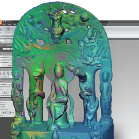
The software then generates a polygon mesh over the point cloud data, accurately transposing the 3D shape into millions of 3d triangles. Autofix functions to remove tiny flaws and anomalies in the data were run by the software, and then mesh regions were generated which identifies surfaces of a similar curvature.
“The creation of mesh regions is an important tool for the 3D creation process,” said Christian. “Since a flat surface would have a different color to a rounded edge, it makes it far easier to identify and edit similar, but different, surfaces.”
While Geomagic Design X can automatically fix most problems with the 3D mesh, some areas that were never scanned or were occluded by other objects have to be identified manually so that the software can repair holes, bumps and so on.
Said Christian, “Another area that needed more extensive cleanup was the deck of the Zodiac. Since we were in dry dock we had a lot of gear such as lines, garbage cans, tools, fenders and other equipment that covered the actual deck surface and which were all picked up by the 3D scan.”
Now the model data is ready to be turned into actual 3D surfaces. Geomagic Design X fits a perfect surface over the mesh region, described by many as like ‘plastic wrap’ stretched over the original mesh and are extended further than the original mesh for trimming purposes.
“If you now create both port and starboard hull surfaces and the deck and transom surface you have 4 surfaces that intersect along the keel and deck lines. With the surface intersect feature you can now trim all the overlapping surfaces, which ultimately result in a full surface model of the vessel.” Said Christian.
According to Christian, the process above is fairly complex, because, when working with accurate real life shapes, things may not simply line up like they should have. Especially with a wood-built, 90 year-old seagoing ship, things are going to shift and change across time.
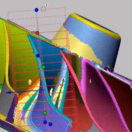
“After I created the initial surfaces they did not intersect smoothly with the keel. Therefore I had to create separate surfaces for the curved part of the hull and the more straight and plane keel surfaces. I only realized that after I used another amazing feature of the software called the Accuracy-Analyzer,” said Christian. “This feature calculates the spatial distance between the mesh and the generated surface and then assigns a color to the distance. It shows you how accurate your model is compared to the mesh that is based on the actual scan data.”
In practice, the color red highlights areas where the distance between surface and mesh is more than 3cm (roughly 1in). Dark blue identifies the same distance in the opposite direction and green shows where the surface matches precisely the mesh.
Now Christian was ready to create 2D sections, waterlines and butt lines by slicing the hull into planes spaced by 3 feet. In the old days when ship builders and naval architects were trying to generate these lines they simply sawed the scale wood models they created by hand with chisels, sand paper and lots of elbow grease into sections. Today, 3D software does exactly the same by slicing the mesh or surface model along parallel planes.
These curves were now exported to 3D Systems’ Geomagic Design CAD software to generate 2D hull lines. The next picture shows the hull curves in Geomagic Design.
“Ultimately, I was able to generate the hull lines which was our initial goal. The butt lines show the deformation of the port hull – if they overlapped 100% the hull would be symmetrical. By comparing the port and starboard section lines we determined that the port side was indented up to 3 inches to the center plane. Creating the hull line drawing is also different since it shows the as-built and aged result, whereas the original design would have had a symmetrical hull.
Said Christian, “I had achieved my main goal of creating the 2D blueprints, but now I found I had something better: a 3D CAD model. This is exciting because now we can use that 3D data to update the CoastGuard stability certification, determine the precise displacement of the hull based on various load situations, create neat virtual walkthroughs for educational and promotional purposes, 3D print the hull, and develop remodeling plans and designs for both the interior and the exterior.”
Christian plans to continue his 3D creation of the Schooner Zodiac, and continuing to use the additional 3D scan data of masts and rigging to create a sail plan, and will be able to develop more detailed plans and models to help this classic ship continue safely in her voyages.