When a stamping die gives out, manufacturing stops – an interruption that major car companies cannot afford to let happen.
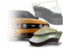
That’s why Ford turned to Detail Technologies to reverse-engineer two Mustang stamping dies that were nearing the end of their life span.
Detail Technologies builds original and duplicate plastic injection molds, stamping dies, compression molds, and individual components.
The company relies on Geomagic Wrap software, which automatically converts point clouds from a scanned physical part into accurate digital models for downstream CAD/CAM and machining.
Most often, tool steels that come to Detail Technologies were originally cut to CAD data, then altered by hand to accurately form the parts. That fine-tuning makes duplication a challenge.
“Stamping steel is not an exact science, and steels are almost always altered from design intent,” says John Amos, a reverse-engineering specialist at Detail Technologies. Eventually these steels need to be repaired, replaced or copied.
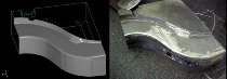
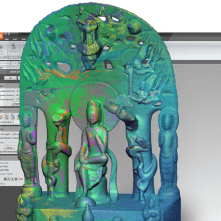
The scanned steels and the matching 3D data created in Geomagic Wrap.
“Unless a customer with great vision obtained the data for future reference,” says Amos, “there is typically no way to reproduce steels without going through the same tedious process.”
That was the position Ford found itself in when the steel tools for stamping and restriking a Mustang cross-member – a part of the frame that attaches the rails – reached the end of their lifecycles. Rather than invest $400 million to retool a Mustang model still on the market, Ford opted to tack on a few more good years by finding someone to rebuild the aging tools before they officially fell out of commission.
Re-building to avoid re-tooling
“Die” is a generic term used to describe the tooling that produces stamped parts. A die set consists of two opposing components that first form, and then punch, holes in steel. The upper half of the die set is mounted on a press ram and delivers the stroke action; the lower half is attached to an intermediate bolster plate, which in turn is secured to the press bed. Guide pins are used to ensure alignment between the upper and lower halves.
Generally, the tools have a projected lifespan of between eight and 12 years.
“Stuff wears down,” says Amos, "and anyone who has seen how stamping works knows that the process is abusive to tools.”
Life expectancy for tools is cycle-dependant – the Ford Mustang is not a huge seller, for example, so its tools would have a longer life expectancy than those for an F-Series truck or an Escape SUV.
As long as demand for the vehicles remains, production will be extended with no change to the structural parts. With each extension, the risk for complete failure increases.
“Someone always has to have the responsibility of saying, ‘allocate the money to make these tools more reliable before we have a disaster,’” Amos says. “The Mustang tools were not broken. They could possibly have run another year or two. But the probability of failure and the cost of that failure outweighed the cost of re-building a couple of tools.”
Creating new tools from old
The two Mustang tools that Ford decided to have rebuilt are used to stamp cross-members that are about 6 feet long and 8 inches wide. Sheets of steel are laid in the first tool, stamped, then restruck with the second tool to further force the corners. A backlog of parts was created to meet requirements while the tools were taken apart, scanned and rebuilt.
Forty-two individual steels were sent to Detail Technologies – 21 per tool – each about the size of a breadbox. They were scanned with a Laser Design, Inc. RPS450 scanner, which has a data collection rate of up to 14,400 points per second. Two data collection sensors operate independently, enabling data that falls in the shadow of some other geometry on the part to be reached.
Amos scanned the steels in their first orientations with each of the two separate sensors then manipulated either the steels or the scanner into another position as needed to collect missed sections. This process was repeated until point-cloud data was collected for complete coverage.
Amos wrote down the coordinates of at least three of the orientation spheres in his final scanned file matrix, and inserted the PH10 probe head back into the CMM to measure 2D data (lines, dowels, screws) as well as the spheres themselves. That enabled a rotation matrix to be created for marrying the files together.
After final scanning, the original tools were reassembled and put back into production. Another backlog of parts was created for when it came time to disassemble and reassemble the new steels.
The final point-cloud data for the steels – each containing 3 to 4 million points – was loaded into Geomagic Wrap, where Amos set the distance sample to .005, and curvature sample to about 70 percent. He shaded the point cloud and isolated any areas that looked problematic. This reduced the point cloud to a more manageable size, while still keeping the points necessary to maintain accuracy.
“Welds on the tool surface cause pitting that will result in an ugly polygon,” Amos says. “The surfaces need to be smooth, or else the tool would show up looking welded again.”
Once rough areas were fixed, Amos continued with a surface wrap – cleaning and relaxing the data to the default settings and eliminating spikes. He isolated the holes – spots where there were voids in the data – and filled them using mathematical controls available in the software.
The resulting surface boundaries were manipulated, constrained and or unconstrained, and shuffled until Amos had a structure that would create accurate workable surfaces. He applied and surfaced grids – usually to the default settings – then created an error map to match the created surfaces with the points from which they were created.
The two data sets were saved as an IGES file and loaded into the MasterCam CAD system, along with a CMM file containing the sphere locations. Amos used the sphere location information to manipulate the two data sets into the same orientation, and extended edge surfaces that were cut off (a trim edge, for example) during the reverse-engineering process. The finalized CAD file was saved for the CAM department.
Archiving data before the fact
The CAM department used the CAD files produced from the steels of the two tools to manufacture blocks that were rough-machined, semi-finished, heat-treated and hard-milled into identical tool replacements. The finalized tools were shipped to Ford and in production after a total of five weeks – four days devoted to the scanning and modeling, the rest of the time to taking apart the tools and manufacturing. The tools were out of production for only 10 days.
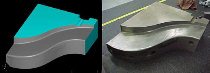
Geomagic Studio was used to create accurate workable surfaces to remake the tools
The amount of time could be reduced even more, Amos says, if manufacturers would make it standard practice to reverse-engineer tools once an approved part is created, ensuring that a digital archive is always available. When a tool approaches its breaking point, the data would be accessed, the tool recreated, and the old switched out with the new.
“We have an extensive file-server system and pride ourselves on being extremely proficient at keeping archived data,” Amos says. “But so often the reverse-engineering work I do revolves around recreating data that a customer can no longer locate. There’s generally no down time available in production tool runs, so when they need it, they need it now. It would be nice if businesses would invest in the security of having a reproducible product up front by scanning tools right after certification. The process would be much more efficient.”