January 2007
3D reverse engineering and digital engineering triggered an evolution for RCR in the 2007 NASCAR event
Kevin Harvick's #29 car is currently in the top five in the Chase for the Nextel Cup. Reverse engineering using Geomagic Design X combined with advanced CFD has dramatically improved the week-to-week performance of the Richard Childress Racing (RCR) team.
As the wins and top-10 finishes accumulated during the 2006 Nextel Cup and Busch Series seasons, theories abounded on what triggered the amazing comeback of the Richard Childress Racing team.
Amid all the public speculation, there was something going on behind the scenes that might be one of the biggest keys to RCR’s new-found prosperity: The team was benefiting from greater use of technologies such as reverse engineering with Geomagic Wrap and computational fluid dynamics (CFD) by engineers who know how to rapidly translate research results into on-track performance.
Technology and Talent
“The combination of great technology and talented engineers who can sift through the data to find the trinkets that make a car go faster is a major factor in the renaissance of Richard Childress Racing,” says John Moloney, general manager of Penske Technology Group, which provides scanning and modeling services for RCR and other racing teams. “Where there have been significant changes in other areas, the engineering behind the cars is where the big evolution has taken place.”
Two of the engineers referred to by Moloney are Chad Zimmer and Noah McKay. Zimmer and McKay are finding new ways to apply reverse engineering and CFD to help ensure consistent performance week after week.
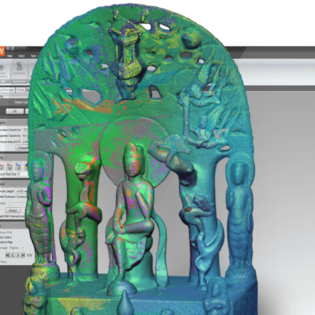
Reverse engineering with Geomagic Wrap refers to the use of technology that enables engineers to navigate seamlessly through physical and digital worlds, creating exact digital duplications of custom-made parts for engineering analysis and rapid manufacturing. CFD has long been used in racing, but RCR is turning it into a more integral tool in the week-to-week preparation of cars and engines.
Zimmer is extending RCR’s work in automated cylinder head porting and CFD simulation to maximize horsepower for its engines. McKay is heading up a program that combines Geomagic Wrap and CFD to capture race car bodies and digitally test aerodynamics under realistic racing conditions. At the center of both Zimmer’s and McKay’s work is Geomagic Wrap, software that enables them to ensure accurate CFD and FEA results for race teams and carmakers around the world.
Duplicating a Hand-Made Crafting
RCR began using Geomagic software for cylinder head porting around 2000. The cylinder port is considered the heartbeat of the engine, and a prime source for generating additional horsepower within Nextel Cup and Busch Series rules.
Traditionally, craftsmen would hand-grind the intricate cylinder heads, customizing them for different types of tracks and racing conditions. The labor-intensive hand grinding would typically take 40 hours for each cylinder head. There were few efficiency gains in grinding subsequent cylinder heads, and it was often difficult to replicate a particularly well-performing head port.
Using Geomagic Wrap enabled RCR to scan a hand-ported head and automatically transform point-cloud data into an accurate surface model in about six hours. Once the first model was created, subsequent ones could be duplicated in minutes. The high-fidelity models gave RCR the ability to accurately recreate a high-performance cylinder head port over and over again with consistent results.
Over the last few years, RCR has made continuous improvements in its reverse engineering implementation, aided by better scanning technologies and methods, ongoing software enhancements by Geomagic, greater hardware processing power, and knowledge built through the experience of half a decade.
The process still begins with hand-grinding of a standard cylinder head port, with the objective to deliver more air and fuel into the cylinders, which in turn increases horsepower. The hand-ground port is tested on a flow bench to determine efficiency. If it passes muster on these tests, it is ready for digital duplication.
Capturing Complex Geometry
Over the past year, RCR has speeded data capture and increased accuracy by using a combination of a CMM touch probe – a Renishaw SP600 system – and a laser scanner. The SP600 is good at capturing precise throat shapes, and collecting data from deep, narrow passages within the cylinder head. The laser scanner makes quick work of capturing all other data in the form of point clouds.
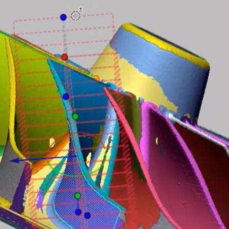
Because of its complexity, it takes as many as several hundred laser scans to capture data for a complete cylinder head. The scans are brought into Geomagic Wrap, where they are registered automatically. The software allows RCR to quickly and easily fill holes and smooth surfaces. Surface reconstruction time is reduced substantially by the patented Geomagic feature of “wrapping” point cloud data to automatically generate a polygon surface. Polygon models can be converted into accurate NURBS surfaces with one click of a mouse or by user-defined layout for interactive surface editing.
RCR creates templates in Geomagic Wrap for surface models of ports and chambers, enabling engineers to mix and match port shapes from past designs and tailor them to the specifications for the current port.
In parallel with processing of laser-scan data, data from the touch probe is brought into Pro/ENGINEER, where the points are lofted to create surfaces. The resulting model is imported into Geomagic Wrap, where patches are created, imperfections removed, and surfaces smoothed. The models generated from the laser and probe data are blended to create a composite surface model.
“More knowledge in less time”
The completed model is sent back to Pro/ENGINEER, where final processing is done for CFD. From there, the model can take two paths: to CFdesign upfront CFD software for a quick evaluation of flow trends, or to meshing in Fluent’s GAMBIT and on to FLUENT CFD software for more in-depth studies of flow characteristics. In both cases, the object is to maximize air and fuel flow and minimize pressure losses.
“The digital tools we have allow us to try more ideas and get the results of changes quicker,” says Zimmer. “We gain more knowledge in less time.”
Based on CFD results, changes are made in Pro/ENGINEER and the design is tested again or finalized for machining in RCR’s dedicated cylinder head shop.
“The combination of laser data acquisition and the ability of Geomagic Wrap to dial into surfaces and get them more exact has given us a better end product in less time,” says Zimmer. “The increased quality of the surfaces is showing up in a lower scrap rate when cutting cylinder heads and more accurate throat positioning, which reduces rework.”
On the all-important performance end, the key word is consistency according to Zimmer.
“When we dyno engines to compare hand-ground ports with those duplicated by Geomagic, they perform identically,” he says. This repeatability extends to subsequent ports produced from the Geomagic template, ensuring consistent performance no matter how many ports are duplicated.
This could help explain the superior performance week to week of the engines in Jeff Burton’s #31, Kevin Harvick’s #29, and Clint Bowyer’s #07 Nextel Cup cars, and Harvick’s #21 and Clint Bowyer’s #2 cars in the Busch Series.
Customizing Aerodynamics
While Zimmer is concentrating on maximizing flow within cylinder head ports, his colleague Noah McKay is taking on the challenge of squeezing out every bit of aerodynamic efficiency possible for RCR’s car bodies. As with almost everything else in stock car racing, a “one-size-fits-all” approach just won’t do.
“The aerodynamics change from week to week, so car bodies have to be customized,” says McKay, citing examples of two different tracks, Bristol and Michigan, where races are held on consecutive weeks.
Bristol, explains McKay, is a short track with the highest banks of any track on the Nextel Cup circuit. In this environment, the focus is on balancing the flow force on the front tires, with less concern about down force. In contrast, Michigan is a fast track with moderately banked curves and long straight-aways. The emphasis is on achieving the asymmetry to push the car to the inside of the curve and generating down force for greater stability.
While in the past there was a considerable amount of guesswork on how body designs would respond to specific tracks, aerodynamics can be much more accurately predicted thanks to the combination of reverse engineering and CFD.
Duplicating the Body Shell
Digital reconstruction of a car body begins with RCR sending an outer shell frame from its Welcome, N.C., headquarters to Penske Technology Group (PTG), about an hour up the road in Mooresville, N.C. Ideally, the car body will arrive with gray primer to reduce reflectivity, but sometimes it will come to Penske complete with decals, in which case engineers apply a thin coat of powder.
PTG has a dedicated scanning bay, with datum reference plates on the floor that can be aligned with their counterparts on the car. Scanning is done with a GOM ATOS white-light scanner from Capture3D.
The ATOS scanner uses white light to project fringe patterns onto an object’s surface. The patterns are captured by cameras positioned on each side of the scanner’s sensor head. Scanning a shell frame of a car takes about five to six hours. Because of the importance of asymmetry in the body design, PTG can’t take the typical short cut of scanning half of the car and mirroring it within Geomagic software; the entire car needs to be scanned.
It typically takes about 20 different scans to capture a car shell. The scans are converged within ATOS software into one large point cloud containing four to six million points, then brought into Geomagic Wrap for decimation and processing. Despite the size differences in the objects scanned, the automated procedures for transforming the car shell model from point cloud to polygons to NURBS surfaces are very similar to those used for modeling laser data from cylinder heads.
Depending on the level of detail required, the Geomagic work takes between a day and a half and two days, according to Moloney.
“We can have a car shell delivered to us on Wednesday morning and prepare a complete CAD model by Friday evening,” he says. “The advances in scanning systems, Geomagic software, and processing power have helped us cut the time it takes to surface a Cup car from about a week and a half to two or three days.”
Determining the “Why Factor”
After receiving the Pro/ENGINEER model from PTG, McKay adds the necessary components to complete the model, including the frame underneath, the engine and duct work, and other parts of the assembly. Depending on how many newly designed parts are needed, this could take anywhere from a few days to a few weeks.
When the full car body is modeled, the data is sent in IGES format to Corvid Technologies, another Mooresville company that specializes in CFD, shock physics and structural mechanics analysis. Unlike other companies that limit the use of CFD for analyzing a design that is already set, Corvid uses CFD as an interactive development tool.
“We use CFD to diagnose changes at the component level and drive development,” says Jimmy Carpenter, Corvid’s director of CFD. “In a wind tunnel, you don’t know why something occurs; the power of CFD is that it reveals the why factor.”
Corvid uses Rhino software to clean up the CAD model for meshing, ICEM to generate the mesh, and its own RavenCFD software for solving large-scale problems at the cell level. The major advantage of RavenCFD is that it is scalable on up to thousands of processors in a Linux cluster; Corvid typically runs CFD problems containing 30 to 40 million cells on its 440-processor cluster.
The Aerodynamics in the Details
CFD testing at Corvid is done as an iterative process: a change is made to a component and then a simulation is run to compare the effects of the change on internal and external wind flow for the car body. The process continues until desired results are reached for each component being tested. Post-processing tools within RavenCFD take the results and analyze them, after which they are presented to RCR as PowerPoint presentations.
“The process has reduced test time in wind tunnels and helped us select paths that reap rewards,” says McKay. “We can test more design configurations and learn more about details that yield benefits.” Those details can include the composition of parts and panels, the optimum height of exterior components, and the positions of components relative to one another.
“Using our current methods, we’ve improved down-force generation by 13.5 percent, results which we’ve been able to validate in wind-tunnel testing,” says McKay. Since down force is one of the most important areas of aerodynamic efficiency in stock car racing, this substantial improvement translates into major performance gains on the track.
A Winning Combination
In Nascar there’s no argument about the impact of technology and equipment in Nextel Cup and Busch Series racing: A car generating more engine power and achieving better aerodynamics will deliver a distinct competitive advantage to its driver and team.
So, while not diminishing the impact of great drivers, personnel, pit crew, and good fortune, perhaps it’s time to give the combination of great technology and smart engineers its due as a major part of a winning formula.
At the time of this writing, RCR has won a title and is closing in on a third-place finish in the Busch Series, and has two drivers in the top five in the Nextel Cup Chase for the championship.
As McKay says, “The racing results speak for themselves.”