July 2006
When the Ferrari 550 Maranello crossed the finish line in front of all other GTS-class cars at the 24 Hours of Le Mans in June, it was not only the car that showed unprecedented speed.
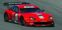
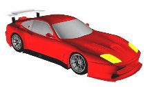
The Prodrive Ferrari 550 Maranello on race day.
The Prodrive-run team won Le Mans in only its second attempt, and had just joined forces with Veloqx five months before the race. In the course of its preparation, the Veloqx Prodrive team embraced new technologies that enabled an alternative rear-wing design in just six weeks.
The new design – developed by Prodrive’s technical partner Advantage CFD in conjunction with 3D Scanners and Geomagic – proved the viability of reverse engineering and computational fluid dynamics (CFD) in a competitive racing environment.
Steep Odds and Little Time
When the Veloqx Prodrive collaboration was announced in February 2003, it was evident that it would be a force at Le Mans. The Prodrive Ferrari had been competitive at Sebring and Le Mans in 2002, and the Veloqx driver line-up was one of the strongest in endurance racing.
But, the odds for winning were still steep. The team was relatively inexperienced, and rule changes for the 2003 Le Mans meant that Veloqx Prodrive was faced with reduced engine power. The changes, combined with increased competition for this year’s race, sent the team in search of improvements in aerodynamic performance, especially drag reduction.
Prodrive turned to Advantage CFD, a company set up in 1997 to provide consultancy services to motorsport and automotive customers. Advantage CFD had to move quickly: the project was outlined in early March and the race was in mid-June. There would only be time for one wing design to be tested before the pre-qualifying event in May.
Turning the Physical to Digital
Although the aim of the project was to study and modify the rear wing, airflow is severely affected by the rest of the car body upstream. That meant Advantage CFD would need CAD data for the entire car body.
“The first hurdle was the fact that we didn’t have a CAD model for the car’s shell,” says Rob Lewis, managing director of Advantage CFD. “We had a week to reverse-engineer the entire body.” And, the job had to be done by companies on separate continents.
Prodrive assembled the required car panels at its Banbury, U.K., headquarters. 3D Scanners, based in Coventry, England, scanned one side of the car using its ModelMaker X hand-held, non-contact scanner with an articulated arm. Everything was scanned except for the front bumper, the only part for which Prodrive had a CAD model.
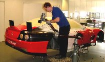
3D Scanners’ Model X with a Faro arm is used to capture half of the Ferrari 550 Maranello body.
Aligned and merged point clouds of Ferrari 550.
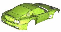
Ferrari 550 Maranello body reverse-engineered in Geomagic Design X (previously Studio) software and assembled and visualized in Pro/E software
The ModelMaker X doesn’t require special lighting or markers, and scans 23,000 points per second. Unlike other technologies, the ModelMaker X had no problems with undercuts when capturing wing mirrors, wheel arches and rear bumpers. Scans were taken from three positions and aligned automatically with the car-line coordinates provided by Prodrive. The full ASCI point model contained 40 million points.
3D Scanners sent eight filtered point cloud files representing half of the Ferrari 550 body to Geomagic in Research Triangle Park, N.C., USA. The company’s Geomagic Design X software automatically processes scan data from a physical part to generate accurate polygon and NURBS surface models. The software had already seen success on the racing scene: it was used by NASCAR team Richard Childress Racing to reverse-engineer engine cylinder head ports and to create a digital model of GM Racing’s SB2 engine block.
Geomagic imported the eight scan files into Geomagic Design X, wrapped the point clouds, and created a polygon mesh. A mirroring function within Geomagic Design X created the other half of the car body that was not scanned, and different sections of the body were stitched together. The software then automatically generated an exact IGES surface from the polygon mesh. The IGES files were sent to Advantage CFD, which imported them into a CAD assembly along with the front bumper data supplied by Prodrive.
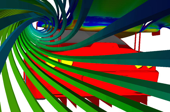
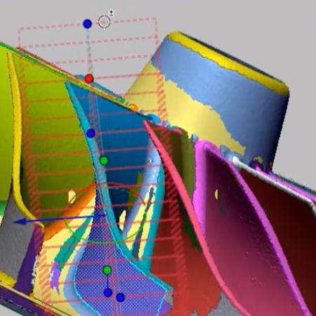
Analysis of airflows with the new spoiler in digital formats allow the design to be perfected prior to manufacturing
Testing Without the Track
Advantage CFD first assembled a complete CAD model of the external geometry for the car. Then, engineers defined a surrounding fluid volume and created a hexahedral mesh extruded from the majority of the body surfaces. A structured hexahedral mesh was also used to resolve the critical rear wing flow, the flow under the flat floor, and the wake behind the car. The remaining volume was filled with tetrahedral cells.
The 3D CFD model was tested initially without a wing to assess flow curvatures around the rear of the car and through the volume where the rear wing is positioned. Based on these findings, Advantage CFD also did 2D analysis on a wide range of wing angles. The analysis showed that the center of pressure for the new wing section should be moved further back.
Advantage CFD then evaluated several new wings on the 3D model, simulating performance at the same speed as used on track tests. Post-processing of the first few design iterations showed regions of flow separation caused by the original wing mounts. Advantage CFD redesigned the wing mounting system to address the issue and ran further CFD tests.
A comparison of oil flow on the rear wings clearly indicated flow separation on the mounts of the original wing, and significant improvement in this area with the new wing design. The new design had a small separation at the trailing edge, but that was removed when a 6-mm gurney was attached to the wing.
Advantage CFD created a final design, checked it at yaw, and delivered the CAD model to Protoform Patterns, which used CNC machines to produce tooling blocks needed to manufacture the new wing.
Track Testing Confirms CFD Results
Prodrive used the tooling blocks to produce a new rear wing in time for track tests six weeks after the project had begun. The track tests and further running at the Le Mans pre-qualifying event confirmed that the new wing reduced drag by 2.5 percent for the same level of downforce.
Lap times at Le Mans test day confirmed what the race itself would later prove: The Veloqx Prodrive Ferraris were easily the quickest cars in the GTS class – with both the new and old wings.
Because of time constraints, Veloqx Prodrive Racing could not test the new wing for durability, a key factor in the 24-hour race. Not wanting to risk going into the race without durability testing, and knowing that its cars were still the fastest, Veloqx Prodrive decided to stick with the old wing design. The wisdom of the decision was borne out by the victory of the young racing team.
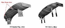
Oil flow on the rear wing and mounts, original wing on the left and the new wing on the right.
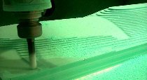
Detailed machining of the course cut lower surface tooling block