To gather vital earth science data around the world, NASA uses an innovative and costeffective unmanned aircraft. Designed by the U.S. Naval Research Laboratory and developed at NASA’s Ames Research Center (Moffett Field, California), the Systems Integration Evaluation Remote Research Aircraft (SIERRA) is routinely deployed for environmental collection missions over remote or inaccessible regions, where harsh conditions and long flights are required.
Challenge:
- Reverse engineer complex engine geometry for design of an improved aerodynamic cowling
- Produce a CAD model utilizing incomplete 3D optical scanning data
- Reduce time needed to produce accurate CAD model, saving time and money
Solution:
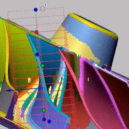
- Scanned the engine using 3D scanner
- Implemented 3D Systems 3D reverse engineering software
- Using 3D scan data of the chassis, created correct hole pattern and solved alignment issue between chassis and tooling fixture
- Reduced time to CAD by 90% (50 hours instead of 500)
The SIERRA has completed missions over the Arctic, lingering for hours at a time in extreme environments to collect data on the polar ice cover. It’s also flown over volcanoes to peer into active craters. NASA’s goal is to increase SIERRA’s 9-10 hour hang time in order to obtain even more valuable information per flight. In order to achieve their goal, NASA decided to redesign the engine cowling to reduce drag and improve fuel economy.
NASA approached MACH-T3 Engineering (www.mach-t3.com) to help solve this challenge. MACH-T3, located in Campbell, California, specializes in 3D solid modeling, finite element analysis, and mechanical design. To accelerate the design process, MACHT3 engineers implement innovative reverse engineering technologies, such as Geomagic Design X software, which converts 3D scans into parametric CAD models.
Challenge: developing an accurate CAD model quickly
To design a more aerodynamic cowling, an accurate 3D CAD model was needed, consisting of all engine dimensions and cowling mounting specifications. Because SIERRA’s engine is an off the shelf aircraft engine, NASA did not own such a model.
Traditional measurement methods for building a 3D CAD model would have been too labor-intensive; NASA engineers estimated that the process would take at least 500 hours. This method involves disassembling the engine, piece by piece, and manually measuring each part. These measurements are then used to manually reconstruct a CAD model of the geometry. Typically, multiple iterations are required in the modeling process, as there will be missing or inaccurate measurements from the original parts.
MACH-T3 took a different approach. “Using a 3D laser scanner and software, we can reverse engineer equipment in a fraction of the time it takes to manually accomplish this task,” explained Bobby Machinski, owner of MACH-T3 Engineering. “Today’s
innovative 3D technology allows us to easily obtain all of the proper contours and quickly produce a CAD model for any part.”
Solution: 3D Systems software
MACH-T3 evaluated numerous 3D scanners and software to add more tools to their business. They chose Geomagic Design X software because it was the only software on the market that could make parametric CAD models from 3D scan data.
Geomagic Design X’s robust features save time
A unique feature of the software is its ability to create a model from incomplete 3D scan data. Optical 3D scanners cannot pick up all data points and render a complete scan due to differences of surface texture, color, and obstructed lines of sight.
“The beauty of Design X is that once you get enough information, you don’t need a hundred percent of the data,” explained Machinski. “Design X recognizes the geometry and allows you to extract model information, even with missing scan data. The software finds the geometric primitives automatically. This capability makes it easy to convert the data over to a CAD solid model, saving time and improving accuracy.”
Deviation analysis is another key feature of the software that saves time. It allows the user to quickly see deviations between the raw scan and the idealized CAD model. “This feature allows us to set tolerances as needed. We can step it up or down to find out how close we are to the ideal model versus the physical model,” Machinski continued. “The software allows us to quickly address deviations that matter to the design, ignore the ones that don’t, and produce a solid model quickly.”
Faster time to CAD
Geomagic Design X software helped MACH-T3 capture the data they needed and quickly develop a CAD model. “The entire project took us 50 hours instead of 500, allowing us to achieve success in only 10% of the time it would have taken us compared to using conventional means,” concluded Machinski. “NASA was ecstatic when we completed the project so quickly. The model of the engine was complete, accurate, and allowed them to make an improved cowling design that perfectly fit around all the engine components of the SIERRA.”
NASA is now one step closer in their redesign of SIERRA’s cowling. Utilizing the detailed and accurate 3D CAD engine geometry to create the new aerodynamic cowling design, SIERRA will soon be conducting even longer atmospheric sampling missions over volcanoes and ice reconnaissance in the Arctic.